1. Продукт закончилсяview
The eletechsup R4IOI16 is a versatile 16-channel multi-function RS485 IO core board designed for various industrial and home automation applications. It supports Modbus RTU protocol and offers flexible configuration options for digital inputs (DI) and digital outputs (DO). This board can be easily integrated into existing IO expansion board systems via its 2.54mm pin header terminal.
Ключевые особенности включают в себя:
- Configurable IO modes: 16DI, 16DO, 8DI-8DO, 4DI-12DO, 12DI-4DO.
- NPN/PNP input and output level switching.
- Wide power supply range: DC 6-25V (main) or DC 4-5V (secondary).
- Компактный размер и легкая конструкция.
2. Что в коробке
Ваша посылка должна содержать следующие предметы:
- 2PCS R4IOI16 RS485 I/O Core Board (Available as 'Only Board' or 'With Pin' versions).

Image: eletechsup R4IOI16 board with pre-soldered pins.
3. Технические характеристики
| Особенность | Описание |
|---|---|
| Номер модели | R4IOI16 |
| Блок питания 1 | DC 6-25V (Anti-reverse protection) |
| Блок питания 2 | DC 4-5V (Reverse connection prohibited) |
| Рабочий ток | 5.6мА |
| MODBUS RTU Function Codes | Write: 05, 06, 15, 16; Read: 01, 02, 03 |
| Configurable IO Modes | 16DI, 16DO, 8DI-8DO, 4DI-12DO, 12DI-4DO |
| Уровни входа/выхода | NPN/PNP Switchable via registers 0X00F5/0X00F6 |
| Режим ввода | Supports 3.3V/5V TTL level input (Low level default, High level option) |
| Режим вывода | 5V TTL level (Low level default, High level option) |
| Communication Anomaly Settings | Restart (0X00F3), Close all outputs (0X00F4) |
| Max Devices (MODBUS) | 247 devices in parallel |
| Состояние входного порта | Query (default) and Automatic Reporting |
| Скорость передачи данных | 1200, 2400, 4800, 9600 (default), 19200, 38400, 57600, 115200 |
| Паритет | Нет, нечетное, четное |
| Интерфейс | 2.54MM pin header |
| Размеры | 51мм х 26мм х 3.8мм |
| Масса | 6 грамм |
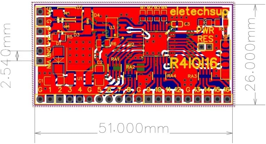
Image: Physical dimensions of the R4IOI16 board.
4. Настройка
4.1 Подключение источника питания
The R4IOI16 board supports two power supply options:
- 6-25 В постоянного тока: Connect to the designated power input terminals. This input includes anti-reverse protection.
- 4-5 В постоянного тока: An alternative power input. Ensure correct polarity as reverse connection is prohibited.
4.2 физическое соединение
The board features a 2.54mm pin header interface, allowing for easy connection using Dupont wires or integration into a breadboard setup. Ensure all connections are secure before applying power.
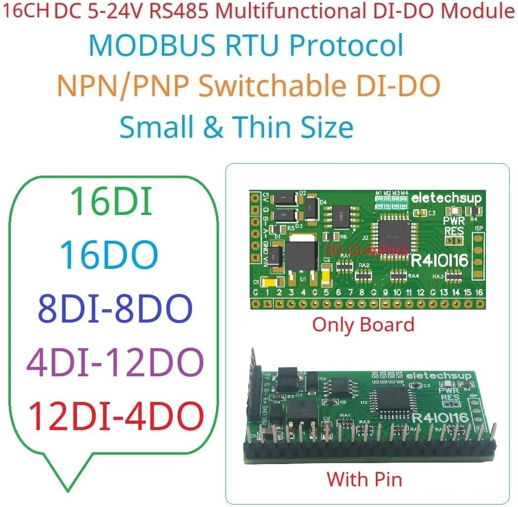
Image: R4IOI16 board showing both 'Only Board' and 'With Pin' versions.
5. Инструкция по эксплуатации
5.1 MODBUS RTU Communication
The R4IOI16 communicates using the MODBUS RTU protocol. It supports standard function codes for reading and writing data:
- Write Functions: 05 (Write Single Coil), 06 (Write Single Register), 15 (Write Multiple Coils), 16 (Write Multiple Registers).
- Read Functions: 01 (Read Coils), 02 (Read Discrete Inputs), 03 (Read Holding Registers).
The board can support up to 247 devices in parallel on the MODBUS network.
5.2 Baud Rate and Parity Settings
The default baud rate is 9600. Other supported baud rates include 1200, 2400, 4800, 19200, 38400, 57600, and 115200. Parity options are None, Odd, or Even. These settings must match the master device for proper communication.
5.3 Input and Output Levels
- Режим ввода: Supports 3.3V/5V TTL level input. The default input mode is low level, with an option for high level input.
- Режим вывода: Provides 5V TTL level output. The default output mode is low level, with an option for high level output.
5.4 Input Port Status
The status of input ports can be queried (default behavior) or configured for automatic reporting, depending on your application requirements.
6 Конфигурация
6.1 IO Mode Selection
The R4IOI16 offers five configurable IO modes, which can be selected using jumpers (0603 0Ω resistor or wire) on the board:
- 16DI: 16 цифровых входов
- 16ДО: 16 цифровых выхода
- 8DI-8DO: 8 Digital Inputs and 8 Digital Outputs
- 4DI-12DO: 4 Digital Inputs and 12 Digital Outputs
- 12DI-4DO: 12 Digital Inputs and 4 Digital Outputs

Image: Visual representation of the five configurable IO modes.
6.2 NPN/PNP Input and Output Level Switching
The input and output levels (NPN/PNP) can be switched by modifying specific registers:
- NPN Input & NPN Output: Register 0X00F5=0, 0X00F6=0 (Default)
- PNP Input & NPN Output: Register 0X00F5=1, 0X00F6=0
- NPN Input & PNP Output: Register 0X00F5=0, 0X00F6=1
- PNP Input & PNP Output: Register 0X00F5=1, 0X00F6=1

Image: Detailed wiring diagrams illustrating NPN and PNP input/output configurations.
6.3 Communication Anomaly Settings
The board provides settings to manage communication anomalies:
- Restart on Anomaly: By setting register 0X00F3, the board can be configured to restart if communication becomes abnormal.
- Close Outputs on Anomaly: By setting register 0X00F4, all output ports can be configured to close when communication is abnormal.
7. Техническое обслуживание
To ensure the longevity and reliable operation of your eletechsup R4IOI16 board, follow these general maintenance guidelines:
- Содержать в чистоте: Regularly inspect the board for dust or debris. Use a soft, dry brush or compressed air to gently clean the surface.
- Условия окружающей среды: Operate the board within its specified temperature and humidity ranges. Avoid exposure to extreme temperatures, moisture, or corrosive environments.
- Перед использованием выключите питание: Always disconnect power before making any physical connections, disconnections, or adjustments to the board.
- Проверьте соединения: Periodically check all wiring and pin header connections to ensure they are secure and free from damage.
8. Поиск Неисправностей
If you encounter issues with your R4IOI16 board, consider the following troubleshooting steps:
- Нет питания: Убедитесь, что блок питания подключен правильно и подает указанное напряжение.tage (DC 6-25V or DC 4-5V). Check for proper polarity, especially with the 4-5V input.
- Сбой связи:
- Ensure the RS485 wiring (A+, B-) is correct and secure.
- Confirm that the baud rate and parity settings on the R4IOI16 match those of your Modbus master device.
- Check the Modbus address of the R4IOI16 and ensure it is unique on the bus.
- Verify that the Modbus commands being sent are correct according to the supported function codes.
- Incorrect IO Behavior:
- Review the jumper settings for the selected IO mode (16DI, 16DO, etc.) to ensure it matches your intended configuration.
- Check the register settings (0X00F5, 0X00F6) for NPN/PNP input/output levels to ensure they are set correctly for your sensors/actuators.
- Verify the input/output signal levels (3.3V/5V TTL) and ensure they are compatible with connected devices.
- Прерывистая работа: Check for loose connections, power supply fluctuations, or electromagnetic interference in the environment.
If problems persist after following these steps, please contact eletechsup customer support for further assistance.
9. Гарантия и поддержка
For warranty information, technical support, or any inquiries regarding your eletechsup R4IOI16 board, please refer to the official eletechsup webили обратитесь в службу поддержки напрямую. Сохраните чек о покупке в качестве подтверждения покупки на случай предъявления гарантийных претензий.
You can visit the eletechsup store on Amazon for additional product information and support resources: eletechsup Amazon Store