
American Volt AV-1022
Universal Electric Radiator Cooling Fan Thermostat Temp Sensor Switch User Manual
Brand: American Volt | Model: AV-1022
1. Введение и обзор продуктаview
This manual provides detailed instructions for the installation, operation, and maintenance of your American Volt Universal Electric Radiator Cooling Fan Thermostat Temp Sensor Switch. This product is designed to automatically control electric cooling fans in automotive applications based on engine or fluid temperature.
The kit includes two temperature sensor switches, each featuring a brass thread-in probe compatible with 3/8" and 1/2" NPT threaded ports. The switch is engineered to activate (ground) the cooling fan when the temperature reaches 180°F and deactivate it when the temperature drops to 165°F, ensuring optimal engine cooling.

Image 1.1: Two American Volt Universal Electric Radiator Cooling Fan Thermostat Temp Sensor Switches. These are the primary components of the product, showing their brass construction and electrical terminals.
2. Особенности продукта
- Двойной пакет: Includes two automotive engine grounding fan temperature switches.
- Temperature Activation: Grounds the fan at 180°F and turns off at 165°F.
- Универсальный зонд: Brass thread-in temperature probe with 3/8" and 1/2" NPT adapter.
- Универсальное применение: Suitable for any application with a 1/2" NPT threaded port.
- Гибкий монтаж: Threads into engine block, radiator, manifold, water outlet, or other suitable locations.
- Совместимость с жидкостью: Capable of measuring the temperature of various liquids, including motor oil.
- Included Connectors: Comes with 2 insulated female wire connectors for ease of installation.

Изображение 2.1: Подробно view of a single American Volt temperature sensor switch. This image highlights the brass probe and the threaded body, which allows for secure installation into various automotive components.
3. Технические характеристики
| Спецификация | Ценить |
|---|---|
| Режим работы | Автоматический |
| Рабочий объемtage | 12 Вольт (постоянный ток) |
| Тип контакта | Нормально открытый |
| Тип разъема | Винт |
| Терминал | Винт |
| Тип цепи | 1-х полосный |
| Тип крепления | Резьбовое крепление |
| Контактный материал | Латунь |
| Международный рейтинг защиты | IP00 |
| Количество позиций | 2 |
| Lower Temperature Rating (Turn-Off) | 165 градуса по Фаренгейту |
| Upper Temperature Rating (Turn-On) | 180 градуса по Фаренгейту |
| Количество единиц | 2.0 Количество |
| Номер детали производителя | АВ-1022 |
4. Настройка и установка
Proper installation is crucial for the correct operation of the temperature sensor switch. Always disconnect the vehicle's battery before beginning any electrical work.
4.1 Выбор места установки
The sensor can be threaded into any suitable 1/2" NPT port that accurately reflects the temperature of the fluid you wish to monitor. Common locations include:
- Блок двигателя
- Radiator (in-tank or hose adapter)
- Впускной коллектор
- Выход воды
Ensure the chosen location allows the brass probe to be fully immersed in the fluid for accurate temperature readings. If your port is 3/8" NPT, use the provided adapter.

Image 4.1: NPT - American Standard Pipe Thread/Taper Guide. This guide helps in identifying the correct NPT size for your application, ensuring a proper fit for the sensor switch.
4.2. Механический монтаж
- Ensure the engine and cooling system are cool to prevent burns.
- Drain a small amount of coolant if installing directly into the cooling system to prevent spills.
- Apply a suitable thread sealant (e.g., PTFE tape or liquid thread sealant) to the threads of the sensor probe.
- Carefully thread the sensor into the chosen port. Do not overtighten, as this can damage the sensor or the port. Tighten until snug and leak-free.
- Refill any drained coolant and check for leaks.
4.3. Электропроводка
The sensor switch operates by providing a ground signal to activate a relay, which in turn powers the electric cooling fan. Refer to the wiring diagram below for proper connections.
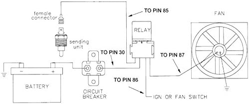
Image 4.2: Typical Wiring Diagram for Electric Cooling Fan Thermostat Switch. This diagram illustrates how to connect the temperature sensor switch to a relay, circuit breaker, battery, and the electric fan for automatic operation.
- Connect to Sensor: Use the provided insulated female wire connectors to attach a wire to the single terminal on the temperature sensor switch.
- Connect to Relay: Connect the other end of this wire to the appropriate terminal on your fan relay (typically pin 85 or the coil ground terminal).
- Power and Fan Connections: Follow the relay manufacturer's instructions for connecting the relay to the battery (via a circuit breaker), ignition/fan switch (if applicable), and the electric cooling fan. Ensure all connections are secure and properly insulated.
- Заземление: Ensure the fan and battery have proper chassis grounds. The sensor switch provides a ground signal to the relay.
Важный: Always use an appropriately rated circuit breaker or fuse in the main power line to protect the circuit.
5. Инструкция по эксплуатации
Once properly installed and wired, the American Volt temperature sensor switch operates automatically. There are no user-adjustable settings.
- When the fluid temperature reaches approximately 180°F (82°C), the sensor switch will close its internal contacts, providing a ground signal to the connected relay. This will activate the electric cooling fan.
- The cooling fan will continue to run until the fluid temperature drops to approximately 165°F (74°C). At this point, the sensor switch will open its contacts, interrupting the ground signal and deactivating the cooling fan.
This cycle will repeat as necessary to maintain the desired operating temperature range for your cooling system.
6. Техническое обслуживание
The American Volt temperature sensor switch is designed for long-term, maintenance-free operation. However, periodic checks can help ensure continued reliability:
- Визуальный осмотр: Periodically inspect the sensor and its wiring for any signs of corrosion, damage, or loose connections.
- Утечки жидкости: Check around the sensor's threaded connection for any signs of coolant or fluid leaks. Tighten if necessary, but do not overtighten.
- Электрические соединения: Ensure the female wire connector remains securely attached to the sensor terminal.
- Чистота: Keep the sensor and surrounding area free of excessive dirt, grease, or debris.
7. Поиск Неисправностей
If your electric cooling fan is not operating as expected with the temperature sensor switch, consider the following troubleshooting steps:
| Проблема | Возможная причина | Решение |
|---|---|---|
| Fan does not turn on at 180°F | No power to relay; Faulty relay; Open circuit in wiring; Sensor not reaching temperature; Faulty sensor | Check circuit breaker/fuse; Test relay operation; Inspect all wiring connections (refer to Image 4.2); Verify engine/fluid temperature with a separate gauge; Test sensor continuity (should show continuity when hot); Replace faulty component. |
| Вентилятор работает постоянно | Sensor stuck closed (grounded); Wiring shorted to ground; Faulty relay | Disconnect sensor wire from relay; if fan stops, sensor is faulty. If fan continues, check wiring for shorts or replace relay. |
| Неточные показания температуры | Sensor not fully immersed in fluid; Air pocket around sensor; Incorrect sensor type | Ensure sensor probe is fully submerged; Bleed cooling system to remove air; Verify correct sensor for application. |
| Fluid leaks around sensor | Insufficient thread sealant; Overtightened/damaged threads | Remove, reapply thread sealant, and reinstall; Inspect threads for damage; Replace sensor or port if threads are stripped. |
Если предложенные способы устранения неполадок не решат проблему, рекомендуется обратиться к квалифицированному автомеханику.
8. Информация о гарантии
Specific warranty details for American Volt products are typically provided at the point of purchase or on the manufacturer's official website. Please retain your proof of purchase for any warranty claims. For the most current and detailed warranty information, please refer to the American Volt official webсайт или свяжитесь напрямую со службой поддержки клиентов.
9 Поддержка
For technical assistance, product inquiries, or support, please contact American Volt customer service. Visit the official American Volt webсайт для получения контактной информации, ответов на часто задаваемые вопросы и дополнительных ресурсов.
American Volt Store: Visit the American Volt Store on Amazon
Ask a question about this manual
Ask about setup, troubleshooting, compatibility, parts, safety, or missing instructions. Manuals+ will review the question and use this page’s manual context to help answer it.